
CNC 3018 Spindle Power Control with Relay
For Christmas last year Jenn got me a SainSmart 3018 CNC router and I’ve really been getting into it. It’s a steep learning curve, a bit more than 3D printing, but my 3D printing knowledge has helped a lot in knowing what sort of things I should look for.
I’ve been getting into it enough that I wanted to upgrade the spindle in it, and my parents got me a Makita RT0701C trim router. This is a fairly common upgrade path - replacing the stock spindle with a Makita or DeWalt router - and you’ll see it in larger setups like the Shapeoko XXL.
IMPORTANT UPDATE: After posting this article I found that, while I was successful in getting the router mounted and generally working in 2D carving (like making letters on a sign), when doing 3D carving I lost Z height a lot. After a lot of trial and error I determined that the SainSmart 3018 PRO does not have strong enough stepper motors to drive the weight of the Makita router. Later models like the 3018PROVer do have the strength, which is why you see so many folks successful with this. For me, I ended up reverting my 3018 back to the stock spindle and upgrading to a Sienci LongMill 30 x 30 which is where I’ve got my Makita router now.
There are two challenges to overcome when you upgrade the spindle to a router like this.
First, you have to figure out how to mount the router to the CNC frame. I solved this by creating a 3D printed combination holder and dust shoe, which you can get on Thingiverse.
Second, you have to change how you turn the power on and off when carving. The stock spindle is powered right off the control board. When you send your gcode to the router, one of the codes turns the spindle on, which sends power to the spindle and it gets moving. A larger trim router like this is plugged in separately and instead of the control board turning it on and off, it’s generally accepted that you have to turn the router on manually with its power switch before you start cutting. Since nothing will be attached to the actual control board power, the “turn on the spindle” command will be effectively ignored.
I… don’t like that. I’m fine if I have to adjust the speed manually on the router, but I would really like the control board to turn the router on and off as needed for the cut. Lots of people, myself included, solve this using a relay. This shows you how to wire it up.
DISCLAIMER: You’re going to be working with electricity. Be safe. Make good connections. Don’t get your fingers in there. I’m not responsible for you burning your house down by making bad wire splices or injuring yourself from touching live electrical stuff. Respect the electricity. This isn’t much more difficult than wiring up a new lightswitch at home, but… just be careful.
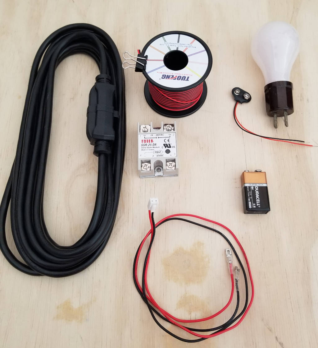
Parts you’ll need:
- One extension cord. It doesn’t have to be very long, you’re going to cut it to get the two end plugs. (Amazon)
- One solid state relay. It should allow an input voltage of 12V DC and an output voltage matching your router (mine is a 120V AC router). I bought a relay that allows 3 - 32V DC input and 24 - 380V AC output so it’ll “just work.” (Amazon)
- Your original spindle power cable. You’re going to cut it because you want the wires and the plastic connector that attaches to the control board. You could also make a new one, but I don’t anticipate plugging my old spindle in again.
- Extra wire in case you want the connection between the control board and the relay to be longer.
- A battery with some leads. The battery should be enough to trigger the relay. I chose a 9V battery which falls in that 3 - 32V DC range. You’ll use this for testing the relay wiring.
- Something to plug in to test the relay wiring. I used a light bulb.
- Solder and soldering iron.
- Electrical tape.
- Wire cutters.
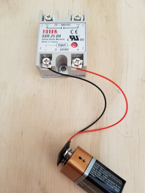
First thing we’re going to do is just make sure the relay is working. This is also helpful to understand how the control board will be turning the router on and off; and it gets your test set up.
Attach one wire to the positive input terminal of the relay and another wire to the negative terminal. Connect your battery to the wires - positive to positive, negative to negative. You should see the light go on to indicate the relay has been triggered. (If you’re usinga mechanical relay, you should hear a click.) When the control board “starts the spindle” it’s going to send 12V in and trigger the relay just like the battery is doing now.
Disconnect the battery. We’re done with this part of the testing.
Cut the extension cord so you can get some wires connected to the plugs. I cut about 12 inches from each end of the cord. That left me with:
- A male plug with about 12 inches of cord
- A female plug with about 12 inches of cord
- A long strand that came from the middle of the cord
You can leave more cord connected to the plugs if you want. Just make sure you leave enough that you can make a good splice and have some slack to plug in. We don’t need that strand from the middle of the cord. You can save it and do something else with it or you can throw it away.
The extension cord will have an outer insulation/wrap and three wires inside it. Each wire also has insulation around it. Likely they’ll be color coded - green is ground, black is “hot” or “active,” and white is neutral. The black and white wires are what effectively makes the circuit powering your router, so we’re going to insert the relay in the middle of one of those to act like a switch. I chose to put the relay in the middle of the white wire.
If you don’t know how to make a good wire splice I would recommend watching this quick YouTube video on how to do a linesman’s splice. You’re working with some real electricity here and a bad splice can cause all sorts of problems like burning your house down.
Splice the two green wires together so the ground is continuous. My router is a two-prong non-grounded plug so it doesn’t use ground, but having this finished is valuable for later, I think. Wrap that splice in electrical tape to make sure it’s insulated from the other wires.
Now splice the two black wires together so the “hot” path is continuous. Again, wrap that in electrical tape so it’s nice and insulated.
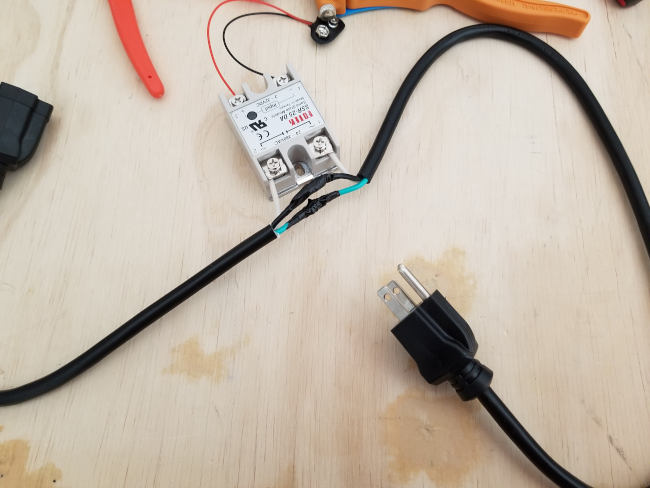
Finally, attach one white wire to each of the “output” terminals on the relay. Make sure there’s a good connection and that they’re screwed down nice and tight.
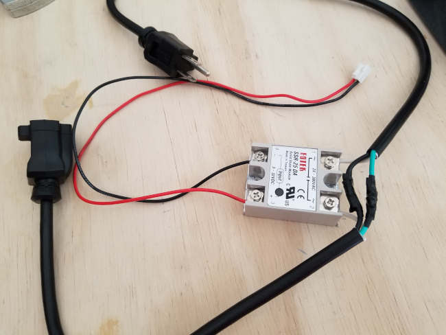
You should end up with something that looks like this:
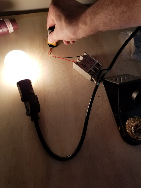
Test time! Now it’s time to make sure your wire splices are good, that things are wired up correctly, and so on. This is also where you’ll want to be extra careful because if you didn’t wire stuff up right, it could be bad news.
Plug in your test load (like I used a light bulb) to the female plug. Then plug in the male plug to an electrical outlet (ideally with a surge protector and/or GFCI circuit breaker for your protection). At this point, even plugged in, the test load (light) should be off. Finally… connect the battery to the input terminals of the relay just like we did in the earlier test. The relay should activate and the test load should turn on! If you remove the battery, it should turn back off.
Disconnect the battery and unplug the relay from the wall and disconnect the wires you were using to test with the battery. The last step is to get the power connector from the control board to the relay working.
If you’re going to make a brand new cable that runs from the control board to the relay, now’s the time. I didn’t do that and I’m not walking through that process.
If you are reusing the original spindle power cable like I did… Snip the metal clips off the ends of the red and black wires that used to power your old spindle. Strip a small amount of the ends of the wire and connect red to positive, black to negative on the relay. It’ll end up looking like this:
That’s it. That’s the whole circuit. Plug this into the wall, plug your router into this, connect the control cable to your control board on the router, and then flip the router switch on. If you use a gcode sender to send M3 that will turn the spindle on. You should see the light on the relay turn on and the router itself should turn on. If you use the gcode sender to send M5 that will turn the router back off.
I recommend putting this in a box or covering it. You don’t want the connections on the relay to get accidentally shorted. I made a quick 3D printed box for mine; you can do something similar or figure something else out. It all depends on the size of the relay and cord you bought, so it’s not one-size-fits-all. If you want to buy a box, search for “project boxes.”
All done, here’s what my setup looks like now:
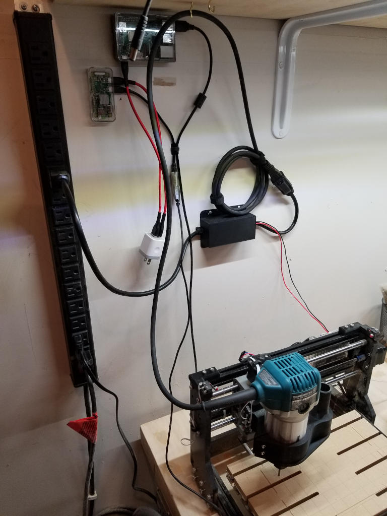
The black box in the middle mounted to the wall contains the relay. It plugs into the power strip along the left. The red and black cables go to the control board. My Makita router plugs into the relay. (I have the cord routed up and hanging so it’s out of the way.)
I hope that helps folks get back some of their control with the upgraded router!
Note: You might be wondering how you can now automated speed control of the spindle, not just on/off. That’s not as straightforward and there are tons of forums involving rewiring routers with variable electronic speed controls (VESC) and all sorts of other cool-but-non-trivial things. I didn’t solve this problem since setting the speed dial before the cut isn’t a huge deal; and I generally don’t change speeds a lot.