
Arduino Volume Monitor for Marantz Receiver
June 2026: There’s an update! I released a new version of this project with better hardware and software.
Our receiver, a Marantz SR5010, is in a cabinet. While it supports on-screen display to show current volume levels and input info, it seems to be fairly well known in the community (e.g., forums, etc.) that getting it to work in conjunction with a 4K display is more luck than skill.
We had no problem with the OSD in standard 1080p HD format, once we got a 4K TV, the OSD basically stopped appearing. Turning everything off and back on again might see it reappear for a 10 or 15 minute span, but after that it disappears.
The challenge: We like to see the receiver’s power/volume/input status but we don’t want to leave the cabinet hanging open.
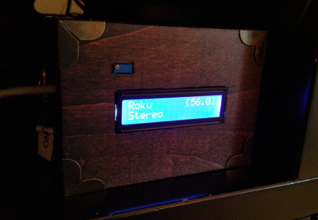
The solution: An Arduino-based volume monitor to provide a remote display for the receiver.
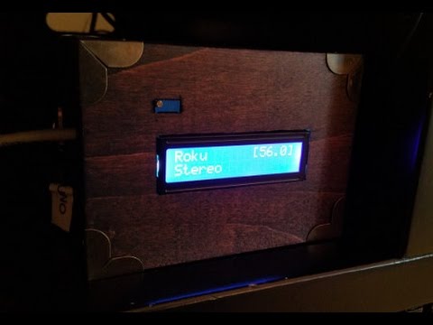
Here’s a video where you can see it in action.
Parts
- Arduino Uno ($10.86)
- 9V power supply ($6.99)
- Arduino 1602 display shield with buttons ($8.49)
- Arduino W5100 Ethernet shield ($15.99)
- Stackable shield headers ($8.49 - you only need one set of these but I bought this three-set pack)
Prices listed are the prices I paid - they may have changed since I bought them, etc.
In that list I didn’t include the box you may or may not want to put the finished product in; and little stuff like solder and a length of wire you’ll need to patch the 1602 shield.
How It Works
Marantz receivers have an HTTP API used for remote control programs and general network interaction. By making a GET request to http://<receiver-ip-address>/goform/formMainZone_MainZoneXml.xml you will get a fairly large XML document that has all the information about the receiver’s current status.
The Arduino volume monitor polls this endpoint and displays values based on the contents of the response.
The basic algorithm is:
- Make a request to get the XML status from the receiver.
- If the receiver is OFF, wait for five seconds before polling again.
- If the receiver is ON…
- Parse the XML to get the volume, selected input, and audio type.
- Update the 1602 display with the latest information.
- Immediately poll again.
The wiki on GitHub where I posted my code has a lot more details on specifically what the Marantz API responses look like and how that works.
Assembling the Hardware
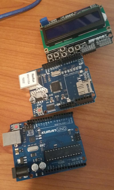
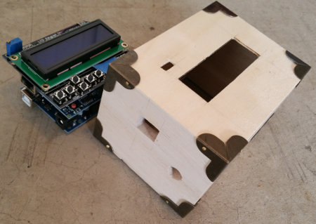
The hardware itself is pretty easy to assemble. We’re going to stack the shields in the order (from bottom to top): Arduino, Ethernet shield, 1602 shield. We’ll do that after we do two things.
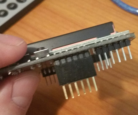
First, we need to patch the 1602 shield. The W5100 Ethernet shield needs digital pin 10 on the Arduino for transmission. The problem is, the 1602 shield (at least the one that I bought) also wants pin 10 for control of enable/disable on the display. If you just stack them up now, things go all haywire - the Ethernet shield never really transmits correctly and the 1602 display basically stays disabled all the time.
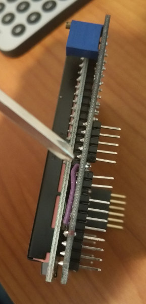
- On the 1602 shield, clip off pin 10. You don’t want the 1602 shield picking up anything from the Ethernet shield. I clipped this off with a small set of flush cutters.
- Solder a small jumper wire across the top of the 1602 shield from pin 10 to pin 3. You could choose a different pin if you like, but pin 3 seemed reasonable.
Now if you want to control the display enable/disable toggle, you can write to pin 3. It won’t interfere with the Ethernet shield and it works great.
In the picture below, you can see me pointing with a screwdriver at the clipped-off pin and my purple jumper wire.
Second, you need to create some risers out of stackable shield headers. The Ethernet jack on the W5100 shield is too tall to just stack another shield on top. I used stackable shield headers to create some small extensions/risers to ensure the 1602 shield didn’t run into the Ethernet jack.
I did clip the stackable header pins down a bit so they sat nice and flush with the Ethernet shield headers.
Now just stack ‘em up and you’re ready to go!
Installing the Software
I published the software on GitHub. You can head over there, grab it, and upload it to your Arduino.
I used the Visual Micro extension for Visual Studio when developing, so you’ll see some Visual Studio files in the source, but you should be able to load it up in the standard Arduino IDE and use it without issue. If you find a problem, file an issue and let me know.
You may need to adjust the button resistance tolerances. In the DFRobotLCDShield.h I have some input values as the buttons are read on analog pin 0. These don’t match the values I saw in any other code snippet or data sheet they posted. I don’t know if yours will match mine, but if they don’t, you’ll have to tweak it.
Using the Software
When you first start up the Arduino it will get a DHCP address and then try to read the configured IP address for your Marantz receiver. If none is configured, you’ll be sent into a setup routine to configure the receiver’s IP address. Alternatively, you can push the “SELECT” button on the 1602 shield keypad and enter the setup routine.
In setup, use the left and right buttons to move the cursor to the right spot in the IP address and up/down to increment/decrement. When you have the IP address entered, press “SELECT” again to save it and continue.
The Arduino will use the receiver’s IP address as the location to make the HTTP GET request as noted above. When the receiver is off, the display on the 1602 will be off; when the receiver is on, the display will be on and showing current data.
It may take a second or two between turning the receiver on and seeing the display come on. This is due to the Arduino only polling every five seconds for status when the receiver is off.
The Arduino is not a super-powered CPU so the data may be delayed by half a second or so. The HTTP request and subsequent processing of the response takes about a half second, give or take. It polls as fast as it can, but that still means you’ll get maybe three updates a second. As such, if you hold down on the receiver’s volume button, you’ll see the Arduino display “jump” in increments instead of incrementing and decrementing smoothly. It also may be slightly behind.
Say you are holding down the volume button on the receiver so it’s constantly going up:
| Time | Action | Arduino Display | Actual Volume |
|---|---|---|---|
| 0.0s | Arduino makes HTTP request | 0 | 0 |
| 0.1s | Receiver sends response | 0 | 1 |
| 0.2s | Arduino starts processing response | 0 | 2 |
| 0.3s | Arduino still processing | 0 | 3 |
| 0.4s | Arduino still processing | 0 | 4 |
| 0.5s | Arduino updates display | 1 | 5 |
The Arduino is going to display the volume at the time the receiver sent the response, which may not be the same volume at the time of display. Not to worry, it should catch up on the next request. At most you’ll be about a half second behind, which isn’t so bad.
Finishing Touches
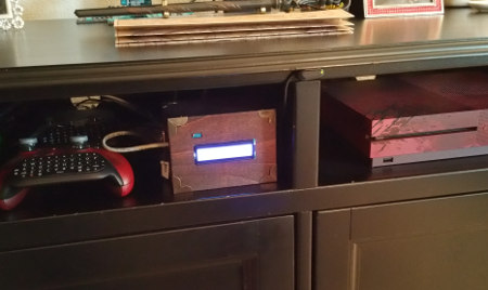
I put my volume monitor in a box. I used one of those little unfinished boxes from a craft store and stained it dark. I padded the inside with a little craft foam to keep it in place.
Once it was all put together, it looked pretty good on the shelf!
Interesting Points
I learned a lot while working on this project.
I was going to do dynamic discovery of the receiver during the setup process so you didn’t have to manually enter the receiver IP address, but that requires UDP multicast to use SSDP. I found out the W5100 series shield doesn’t support UDP multicast… or if it does, I couldn’t get it working. There really aren’t any examples out there. All the standard Arduino Ethernet library support for UDP multicast seems to be for the later W5500 shield.
I noticed that a lot of projects skip the “nice UI” thing and hardcode a lot of stuff. For example, most projects seem to hardcode destination IP addresses right in the program. I suppose that’s fine, but if (for whatever reason) I need to change the receiver’s IP address, I really don’t want to have to reprogram the Arduino. That’s why I put the setup UI in there, though it does take some of my program space and RAM to support its existence.
Since you only get 2K of RAM to work with, the Marantz HTTP response being in XML was challenging. Even if it was in JSON, it’d still be far too large to read in its entirety so I had to do some pretty basic string parsing to read the XML and process it as a stream. I’m kind of surprised there aren’t SAX parsers for Arduino, though I suppose these projects generally avoid XML altogether.
The Repository
The code is all free on GitHub. I included a lot of more technical info in the wiki for that repo.
Go check it out!